In high-speed and mixed-signal PCB design, crosstalk is one of the most common causes of signal integrity degradation. Many engineers treat crosstalk as an unpredictable phenomenon to be measured and corrected during lab testing or post-layout simulation. However, crosstalk is a highly predictable physical phenomenon determined by trace geometry, meaning it must be resolved during the layout phase rather than as a post-layout patch.
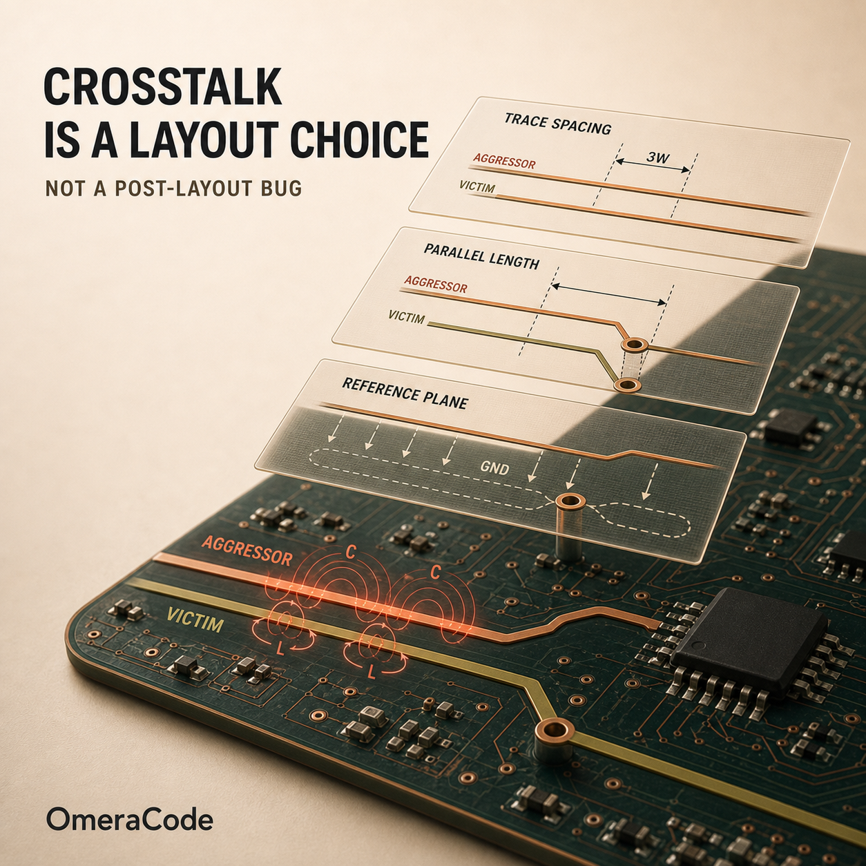
Crosstalk occurs due to capacitive and inductive coupling between an aggressor trace and a victim trace. To mitigate this effectively, designers must understand the physical mechanisms behind its two primary components:
- Near-End Crosstalk (NEXT): This noise propagates in the direction opposite to the aggressor signal, flowing back toward the driver of the victim trace. NEXT increases with parallel coupled length up to a critical threshold (saturation length), beyond which it remains constant.
- Far-End Crosstalk (FEXT): This noise propagates in the same direction as the aggressor signal, traveling toward the receiver of the victim trace. FEXT increases linearly with parallel coupled length and is heavily influenced by the homogeneity of the surrounding dielectric.
Three primary geometric variables control the amplitude of NEXT and FEXT during layout:
1. Trace Spacing and Electromagnetic Field Decay
The electric and magnetic fields surrounding a trace decay rapidly with distance. Increasing the spacing between adjacent traces is the most effective way to reduce field overlap and lower coupled energy. Standard guidelines include the 3W rule (where center-to-center spacing is at least three times the trace width) or the 3H rule (where spacing is at least three times the dielectric thickness to the reference plane).
- The OmeraCode Solution: OmeraCode’s design constraint system defines custom spacing rules for high-speed and sensitive net classes. During the routing phase, OmeraCode’s auto-router automatically calculates and enforces these spacing clearances across all signal layers.
2. Coupled Parallel Length and Stackup Stratification
Since FEXT accumulates linearly with coupled length, minimizing parallel routing runs is essential for clock signals, high-speed differential pairs, and sensitive analog tracks. Furthermore, the selection of the PCB stackup configuration dictates FEXT behavior:
-
Microstrip (Outer Layer Traces): Traces on the outer layers experience an inhomogeneous dielectric medium (FR4 substrate below, air above). This difference causes the electromagnetic propagation velocities of capacitive and inductive coupling to mismatch, generating a substantial FEXT voltage.
-
Stripline (Inner Layer Traces): Traces embedded inside the substrate between two solid reference planes experience a homogeneous dielectric medium. In this configuration, the capacitive and inductive coupling coefficients balance out, theoretically driving FEXT to zero.
-
The OmeraCode Solution: OmeraCode’s routing algorithm automatically limits parallel trace runs of sensitive net classes. Additionally, during stackup configuration, the system prioritizes routing critical high-speed traces on internal layers (striplines) rather than outer layers (microstrips) to eliminate FEXT at the source.
3. Reference Plane Quality and Current Return Paths
A continuous ground (GND) plane adjacent to the signal layer provides a low-impedance current return path. High-frequency return currents naturally flow directly underneath the signal trace to minimize loop inductance. This confines the electromagnetic fields between the trace and the reference plane, shielding adjacent traces from unwanted energy coupling.
- The OmeraCode Solution: During stackup configuration and copper pouring, OmeraCode automatically allocates solid reference planes and applies continuous ground pours around sensitive traces to ensure shield effectiveness.
Conclusion
Discovering crosstalk issues during physical board testing often forces a complete redesign, delaying project schedules by weeks or months. By embedding geometric layout rules and physical stackup considerations directly into the automatic routing pipeline, OmeraCode resolves crosstalk at the layout phase, ensuring optimal signal integrity before the design reaches the final manufacturing gate.
#PCBDesign #SignalIntegrity #Crosstalk #OmeraCode #EMC #DFM #HighSpeedDesign